HomeLab Networking Part 1 - The VLANS - There and Back Again
Backstory
My history with ISPs in my home city of Mumbai has been rocky. Way back in 2005 when I moved here, ADSL was mainstream, with the fastest speeds being 256 kilobits/s. After suffering for a year on a wireless CDMA-1x wireless landline with pay-per-minute internet access, we got a MTNL ADSL connection to our apartment complex. Over the next few years, the blazing fast 256kbits/s dialup line served me well, if a little frustratingly due to the horrible customer service by the government-owner MTNL during the downtimes that were bound to occur over delicate POTS lines. Latencies were of the order of 60ms to the local ISP node, but it was still better than a wireless connection.
The peace of mind granted by not having to worry about overage charges or even-slower internet after crossing Fair Usage Policies, cannot be understated. At some point, 2megabits/s (yay!) FUP-capped plans (boo!) became available, but I insisted on a slower 512Kbps-in-the-daytime-1Mbps-in-the-evenings-2Mbps-at-night unlimited usage, plan. Many a nights went by scripting ADSL modem restarts and file-download resume managers to take advantage of the timed speeds.
A few more years passed, and private players started to come into the picture - Hathway Broadband (over DOCSIS) and Airtel Broadband (still over ADSL) became available. 25mbps and 50mbps FUP-capped plans provided by Hathway were still on the expensive side, and I used their 10mbps plan for a couple of years, with the FUP varying from 80GB to 200GB per month. Latency to the local ISP node over the DOCSIS cable connection was around 20-30ms, and it was clear ADSL was on its way out. I still missed uncapped internet, but there was simply no other choice. The fast/cheap-ish unlimited plans by players like Hathway were restricted to cities like Bangalore and Hyderabad, which was confusing to me because I’d expected that it would be easier for ISPs to provide cheaper/better service in Mumbai, being an international cable landing port. Download:Upload bandwidth ranged from 10:1 to 5:1.
Competition from private players over the next couple of years scared Hathway into bumping up the FUP cap on plans to over 1 terabyte, and reducing prices, in an attempt to prevent users from defecting to the much-hyped in-perpetual-beta private player JioFiber. I switched to a 50mbps plan, and all was good, atleast for a year or two. After that, it became clear that Hathway’s technical support was laughable at best, mind-numbingly frustrating at worst, and frequent downtime and less-than-promised speeds had made my family rather bothered.
This year, after I got a job, I had had enough of Hathway’s service getting worse. JioFiber was still nowhere in sight, and Airtel broadband was inexplicably still on bonded ADSL upto 16mbits/s. In the search of an alternative, I stumbled upon a local ISP named Net4U, that I had somehow overlooked in our area. They provided plans upto 200Mbps over Ethernet to the home, from their fiber-to-the-building junction. Best of all, the plans were fully unlimited, with upto 50Mbps upload on 100Mbps and above plans. The 200mbps plan was (and still is) too expensive, and so I quickly went for the 100Mbps sweet spot plan. Unlimited data transfer, with 1-3ms latency to the ISP node in the city, and I finally felt like I was living in a “Tier 1” city.
This brought me to the next stage of my journey - the real homelab setup could begin, with my two systems behind a managed software firewall and router, backed by decent internet service.
My network layout
My apartment is a three bedroom + hall + kitchen layout flat, with internet and cable drops coming to the central hall’s corridor overhead-hatch-panel-thing. My bedroom is adjacent to this panel, with a door in between. The usual connectivity setup in this layout was to have the wifi router mounted in the hall corridor, serving the two adjacent bedrooms, the hall and dining area, and the 3rd bedroom beyond the the hall. This was problematic since basically no wifi access point’s range would stretch beyond the end of the hall, stopping short of the 3rd bedroom. The hall and dining area would have great connectivity, but there were dead zones in the two bedrooms the corridor connected to. The far end of my bedroom had pretty weak coverage due to the layout of the walls, and there was a solid one third of the other bedroom that didn’t have a stable wifi connection because there were two walls and a bathroom between it and the access point in the hall. I used an old wifi router as a repeater placed at the far end of the hall so that the 3rd bedroom had passable connectivity.
All these years, with only laptops and phones to connect, this setup worked fine. But with a desktop built, and homelabby stuff to be done, I didn’t want to rely on wifi. For the first week or two after I assembled my PC, I used a 15 meter CAT6 Ethernet cable running across my room, out the door, connected to the wifi router mounted on the wall, just dangling there. My parents were a bit miffed about this, and I actually did trip over the cable a few times.
My room had a RJ11 jack intended for an intercom connection, back to the hall junction, but it was on the other side of the room from my desk where the desktop and laptop would be. Interestingly, the RJ11 jack was actually backed by a two pairs of a 4 pair CAT5 cable, so I replaced it with an RJ45 jack and wired up the other end with a ethernet connector to plug in to my switch. Now the 15 meter cable to the desktop no longer had to go out of my bedroom, only across the room along the walls. The in-wall CAT5 cable was never intended for this though, so the even with all four pairs wired up, the link to the hall would drop after a few hours from gigabit to 100mbit, due to the poor quality cable (my bad crimping and jack termination skills probably didn’t help matters). There was also a coaxial TV cable from the hall junction to my desk, intended for a satellite TV box. I wasn’t too pleased about the few ethernet over coax adapters I tried to find, so I wanted to replace that cable with a proper ethernet cable. It was a tight fit and many electricians over the years had refused to do the job, but after a couple of months we managed to find an electrician willing to put in the extra effort to replace the coax cable with two CAT7 Ethernet cables. CAT7, because “futureproofing” and “why not?”, and two, because I doubted any electrician would want to deal with the tight tubing again if I ever needed another cable put in.
While this electrician-from-heaven was around, we also decided to pull an Ethernet cable to the hall TV “desk” so that I could use the wifi router I was using as a wireless repeater for the out-of-hall-range 3rd bedroom, as a wired access point instead. This would reduce congestion on WiFi and up the speeds my parents would get in that bedroom. This is what one of the TPLink Gigabit Ethernet switches was for - it went in the hall junction and provided ports to connect the TV desk AP with the junction, and the ISP modem, and the devices in my bedroom.
I also wanted my laptop to be on a wired connection to the network, and it would be a lot more flexible to have it and the desktop connected to a switch on the desk which would be connected to the hall by the in-wall cables. This is where I used the other TPLink switch. I only connected a single cable of the two new cables between the hall switch and my room switch, for now, but the switches supported link-aggregation, so I could do that later if I wanted to. (Narrator: He did.)
The third betroom also had a similar CAT5 cable running to an RJ11 jack. I later replaced that RJ11 intercom jack with a RJ11 + RJ45 panel, using two pairs for the RJ11 intercom and the other two pairs for 100mbit Ethernet. My parents wouldn’t need gigabit connectivity to their room, but they did need the intercom drop, so gigabit couldn’t be accomplished over just a single 4 pair wire.
High availabilty (CARP)
All of this was a flat physical network, but a double-NAT logical network, with the ISP modem’s DHCP and DNS disabled, since my pfSense VM on the desktop or laptop handled that and was to be the gateway for all user devices. The pfSense VM’s WAN was just a static IP on the ISP modem’s LAN, with DMZ (all ports forwarded to it), since there was no bridge mode option in the cable modem.
The ISP modem had a public IP on its WAN, and its LAN address was 192.168.1.1/24. The pfSense VM on the laptop had its WAN configured to be 192.168.1.11, with the LAN address being 10.0.0.2. I ran another pfSense VM instance on the desktop, with a WAN address of 192.168.1.12, and the LAN interface on 10.0.0.3. I set up CARP on pfsense, for high availability. The CARP WAN virtual IP was 192.168.1.10, and the CARP LAN virtual IP was 10.0.0.1. DNS and DHCP had these IPs configured, and 192.168.1.10 was set as the DMZ in the ISP modem. The laptop pfSense was configured as the primary, and in normal operation, it would have ownership of the CARP address and perform routing and state management.
If my laptop was shut off or disconnected from the LAN network because me or my parents needed it for something else in a different room, the pfSense instance on the desktop would assume ownership of the CARP virtual 10.0.0.1 and 192.168.1.10 IP addresses, providing seamless internet connectivity to the 10.0.0.0/24 LAN devices. Similarly I could turn off my desktop to tinker with the hardware and my laptop would be remain the primary CARP virtual IP owner and provide all of pfSense’s functions. This added a lot of needed flexibilty and allowed me to run a pfSense-based network without interruptions, and I didn’t have to tell everyone the internet would be down for 15 minutes because I was using the laptop or the desktop for something else. Otherwise, I would have had to let the ISP modem be the sole router, with a lack of features and control.
Weird problems
This seemed to work fine for a few weeks but occasionally my parents complained of websites failing to load and connections just dropping occassionally. I chalked it up to Hathway’s network causing issues again. While I was at work, my parents would restart the Hathway modem in frustration, and that would apparently solve it for a few hours, but I had no info to go on. My dad said some of the finance and news related sites would stop working, but he would have reset the mdodem by the time I was home and sites that I opened (wikipedia, google, facebook, etc) seemed to work fine.
One evening while I was at home, browsing Youtube and scrolling through Instagram on my phone, I noticed Youtube failing to load in a new tab and lots of pictures on Instagram just staying empty (not even the loading placeholder icon). I had been noticing the Instagram problem over what felt like a couple of weeks. Annoyed, I opened up a logcat app on my phone, hoping Instagram would be putting out atleast some error messages in the log that it wasn’t showing on the app, and I saw HTTP requests to image and advertising URLs timing out. When I opened the same ad/image URL after disconnecting from wifi, everything loaded fine. I connected back to wifi and all instagram.com resources started timing out again. I realized the issue my parents were telling me about was recurring and I started debugging. HTTP requests to these sites would simply time out, and it wasn’t limited to a single site, but whatever I had been using previously just a few hours ago. Debugging the issue showed that packets destined to their IPs would face a TTL expired error. Wait, what?
A traceroute when the network was in this bugged state, would show the first hop to be the pfSense gateway (10.0.0.1), then the ISP modem LAN gateway (192.168.1.1), and then nothing after that. Doing a traceroute from pfsense showed packets not going beyond the ISP modem LAN gateway (192.168.1.1). Then I opened up the ISP modem’s diagnostics page - a traceroute there showed the next hop for those IPs to be my pfSense WAN interface’s address (10.0.0.1). This was weird - why were the packets intended for the ISP WAN going back to my pfsense box, in a loop? Restarting the ISP modem would fix this and the next hop for everything would then be the Hathway WAN side gateway, but after a few hours or half a day, this would keep recur. It looked like running a double NAT setup on the the flat physical network layout was causing problems - something on the ISP modem was deciding after a while that the right next hop for destinations was the pfSense device on its LAN. There wasn’t any “smart” feature in the ISP modem software doing this, atleast none that I could see configuration for. Further looking around and asking a colleague at work brought up a candidate - ICMP Redirects. I wasn’t sure if this was what was happening - it seemed to explain it. I set up a few firewall rules and config toggles on pfSense to block and log ICMP redirect packets, but didn’t seem to come across any, so I might have not done that correctly. After a bit of failed effort, and knowing the fact that this sort of flat layer 2 network wasn’t a good idea anyway, I decided to move on to a proper solution.
I would have to properly isolate the two logical networks to deal with this. The problem was, I needed the pfSense LAN to span both my room switch (attached to my desktop and laptop) and the hall switch (attached to the hall wifi AP and other devices). The WAN connection from the ISP modem also had to span both switches to get from the hall junction to my room where the desktop and laptop were running pfSense. I had run two cables between the hall and room switches, so I could dedicate one of them to be directly connected to the ISP modem’s ethernet port, with the other end to the room switch on a port configured as a different non-native “port-based VLAN”, and then attach a virtual NIC to my pfSense VMs tagged with that VLAN. However, this meant I would always be limited to a single gigabit link for traffic between the two switches, and the pfSense-hosting virtualization hosts would have to be connected to my room switch with no flexibility because I would be dedicating a physical in-wall link to that purpose. If I ever got a second internet connection cable drop to the hall junction, I would have no more links to my room to run it over.
There was no need for these compromises - basically all “smart” Ethernet switches support “802.11q VLAN tagging” in addition to “port-based VLANs”.
VLANs - the clean solution
VLANs are a separation of logical networks over the same physical network. Each VLAN is identified by a VLAN ID, and any packet can be tagged by the sender NIC or the receiving switch to belong to a certain VLAN. In my case, the ISP modem was a VLAN-unaware device, so the TPLink switch would have to be configured to tag all packets received on the connected port to a VLAN ID, and similarly untag all the VLAN ID from all outgoing packets on that port. The ISP modem would see on its network only devices configured to receive the same VLAN ID (I set Hathway to VLAN 99), which would be only the pfsense VMs. If I got another ISP, I would simply tag its port with a different VLAN ID (say, VLAN 98), and configure pfSense with a virtual NIC to recieve that VLAN.
This freed me to have any number of WAN connections on any free ports on the hall switch, and use both of the cables between my hall and room switch in a Link Aggregation Group (LAG). I would have a total bandwidth of 1+1 gigabit per second across atleast two data streams, which could be any combination of intra-LAN traffic (streaming media from my room to the TV in the hall, etc) or LAN-WAN traffic (downloads and uploads from the internet).
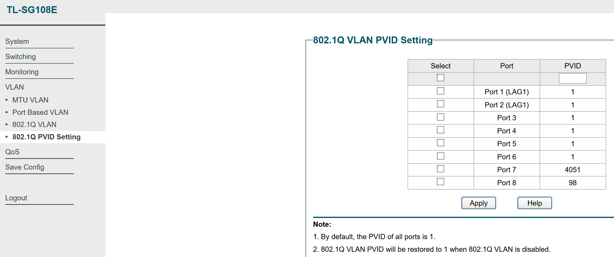
This was the first time I had worked with VLANs, so it did take me some trial and error to understand the terminology used by different guides online and what settings they corresponded to in my “Easy Smart” TPLink switch. I spent a few hours trying to get the tagged and untagged and member VLAN configurations knowing I was missing a part of the puzzle. The main AHA moment was when I understood that “native VLAN for a port” or “Access port” in Cisco terminology meant setting the “PVID” of the port in a separate tab in the TPLink Switch web settings GUI.
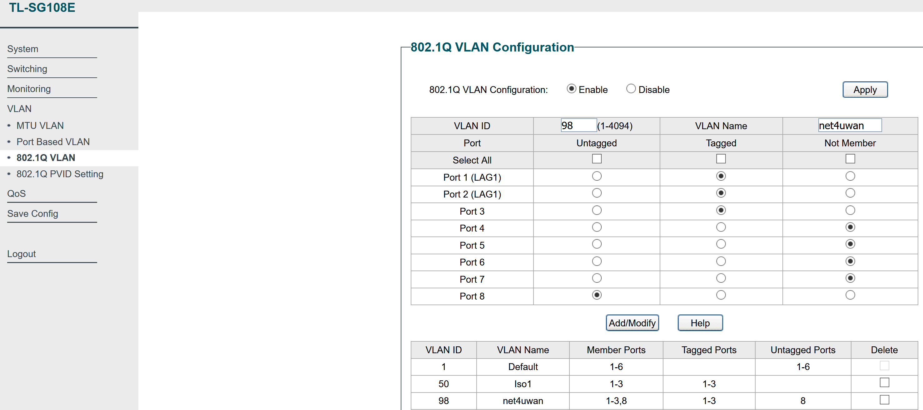
Here’s an indicative config of my hall switch, for posterity and to help any readers that are new to this and want a full config as an example. The WAN ethernet cable is plugged into Port 7 of the hall switch, and I’ve decided to use VLAN 98 for this WAN.
The port on the room switch where my virtualization system (which will be running pfSense), is set to receive this VLAN as tagged.
802.1Q VLAN config:
PVID config:
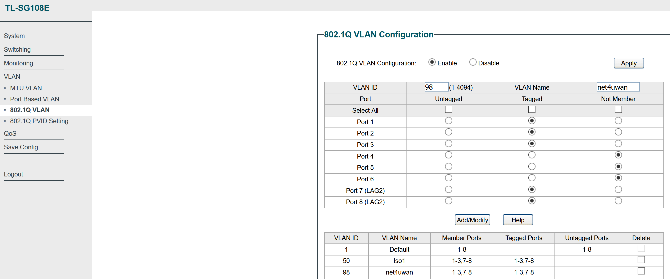
Room Switch:
This can similarly be extended to have any configuration of layer-2 networks spanning across the set of VLAN-aware switches and devices connected to their ports. With Proxmox (in a later blog post), managing VLANs for virtual machines and linux containers you run is a breeze - just configure the virtual NIC for your VM/container with the VLAN ID, and make sure all switch ports between that Proxmox host and any other Proxmox hosts or devices, have that VLAN ID tagged on the switch port.